PolySDL-STRUCTURAL DESIGN LAB
at Florida Polytechnic University
Active learning in Civil Engineering through structural design, modeling, testing, and experimentation
Built-up timber beams in action
A hands-on exploration of transverse shear, connection behavior, and experimental beam response

Why This Activity Matters
This activity helps students move beyond textbook calculations and observe how a real built-up beam behaves under load. It highlights the importance of connection details, force transfer, stiffness, and experimental response.
Activity Status
In Development
Main focus
Transverse shear. Shear flow, Connection Behavior
Course Connection
Statics, Strength of Materials
Tools / Platforms
AutoCAD, Hand Calculations, Physical Testing, Reaction Frame and Load Actuactor
Activity Type
Design-Build-Test
Team Format
Groups of 5
Mode
Physical
Key Deliverables
Construction drawings, Load Prediction, Fabricated Specimen, Reflection Report

Technical Snapshot
-
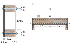
Structural system: Double-web built-up timber girder with solid-wood top and bottom chords and plywood web panels
-
Planned test span: 8-ft simply supported beam
-
Cross-section concept: Two ½-in plywood webs connected to 4 × 6 timber members at the top and bottom
-
Loading configuration: Concentrated midspan load applied through the Structural Design Lab loading system
-
Primary design variables: Mechanical-fastener type and longitudinal fastener spacing, s.
-
Force-transfer mechanism: Fasteners transfer longitudinal shear between the plywood webs and timber chords
-
Analytical basis: Bending stress, transverse shear, shear flow, and fastener force calculated from q.
-
Responses studied: Load capacity, stiffness, connection slip, deformation, and observed failure mode
-
Experimental comparison: Predicted maximum load compared with the measured test capacity and behavior
The Design Challenge
Student teams develop and test their own built-up double-web girder specimens by varying connection details, with fastener spacing serving as the primary design parameter. Some groups may also compare screw-connected and bolt-connected configurations. Each team prepares AutoCAD construction drawings, selects materials, predicts the maximum load the beam can carry, fabricates the specimen, and tests it under midspan loading in the Structural Design Lab.
The completed girders are evaluated experimentally using the lab’s loading system, and the measured behavior is compared with analytical predictions. Students then reflect on the relationship between theory and experiment by documenting observations, test results, failure behavior, and lessons learned.
Full details regarding group variations, specimen geometry, materials, connection type, analytical prediction, fabrication, testing, and final deliverables are provided in the Structural Design Lab Activities Handbook.
Related Photos and Project Examples
 |  |
|---|
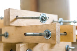
Selected images from related fabrication, testing, or previous project examples.